03 Sep Input Buffer for Hypex NC1200
We offer our customers a Buffer for the Hypex NC1200 module in kit form, so that the most expert users who already have the Hypex NC1200 power modules, can install them thus improving the sound quality. This Buffer includes SIL994 Enh Ticha operational amplifiers from Sonic Imagery. These operational amplifiers are characterized in that they operate in class A, providing a very warm sound similar to vacuum valves. The buffer card is ready to be able to insert other operational amplifiers, such as Sonic SIL990 or Sparkoslabs SS2590, used in professional audio and recording studios. The JRC MUSE series, AD and OPA series of instrumentation and discrete operational amplifiers can also be used. When carrying a socket, they can be exchanged so that the sound differences between them can be audibly compared. Only dual operational amplifiers (dual amp op) can be inserted into the socket
The printed circuit board of the buffer has been developed in such a way that it adapts physically to the NC1200 module of Hypex, mounting in the form of a turret so that it does not take up more physical space inside the amplifier, only a few millimeters of elevation. (see photos of the assembly) This board is only valid for the V4 and following of the NC1200 module (currently V6)
The use of this kit requires technical knowledge from the user. The equipment where the NC1200 modules are housed must be disassembled and modifications must be made to those modules. This requires a welder to make a welding bridge. This modification is indicated in the NC1200 module service manual that can be downloaded from the Hypex website at this link:
https://www.hypex.nl/img/upload/doc/ncore/nc1200/Documentation/NC1200_datasheet_R10.pdf
It is also necessary to feed the buffer. To do this you have to locate a point where there is a supply of +/- 17 to 30V and solder the cables to the connector supplied in the kit. If the NC1200 module is powered by the manufacturer’s own source (SMPS1200) it will be easier because the source has a connector that provides the power.
This buffer is compatible with the power amplifiers of Theta Digital, March Audio, Apollon Audio, Nord Acoustic and Rouge Audio. Mola Mola uses a physically modified Hypex NC1200 module, so this buffer is not valid, but a physical modification can be made on the board to adapt it. If you are a Mola Mola owner, contact us to give you more information about it.
Next, we will describe the steps for installing the buffer. A paper installation manual is included with the kit.
Installation: NC1200 Buffer Kit
Proceed to
disassemble the amplifier to access the interior.
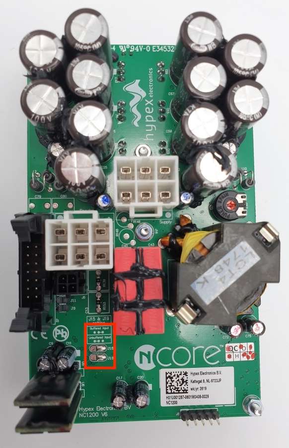
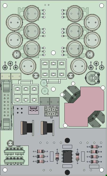
NOTE: Before using this Buffer with the Hypex NC1200
module, it is necessary to make a small modification to the module, as
indicated on page 11 of the service manual. It is about changing the position
of the jumpers of connectors J15 and J19 to the “Unbuffered Input” position.
See figure 1 marked in red.
The NC1200 Buffer Kit consists of the following components for two-channel stereo mounting:
- Two NC1200 v1.0 Buffer printed circuit board
- Two Sonic Imagery SIL994 Enh Ticha operational amplifier.
- Two connectors for +/- 15V power
- Four 15mm spacers
- Four 6mm metric M3 screws
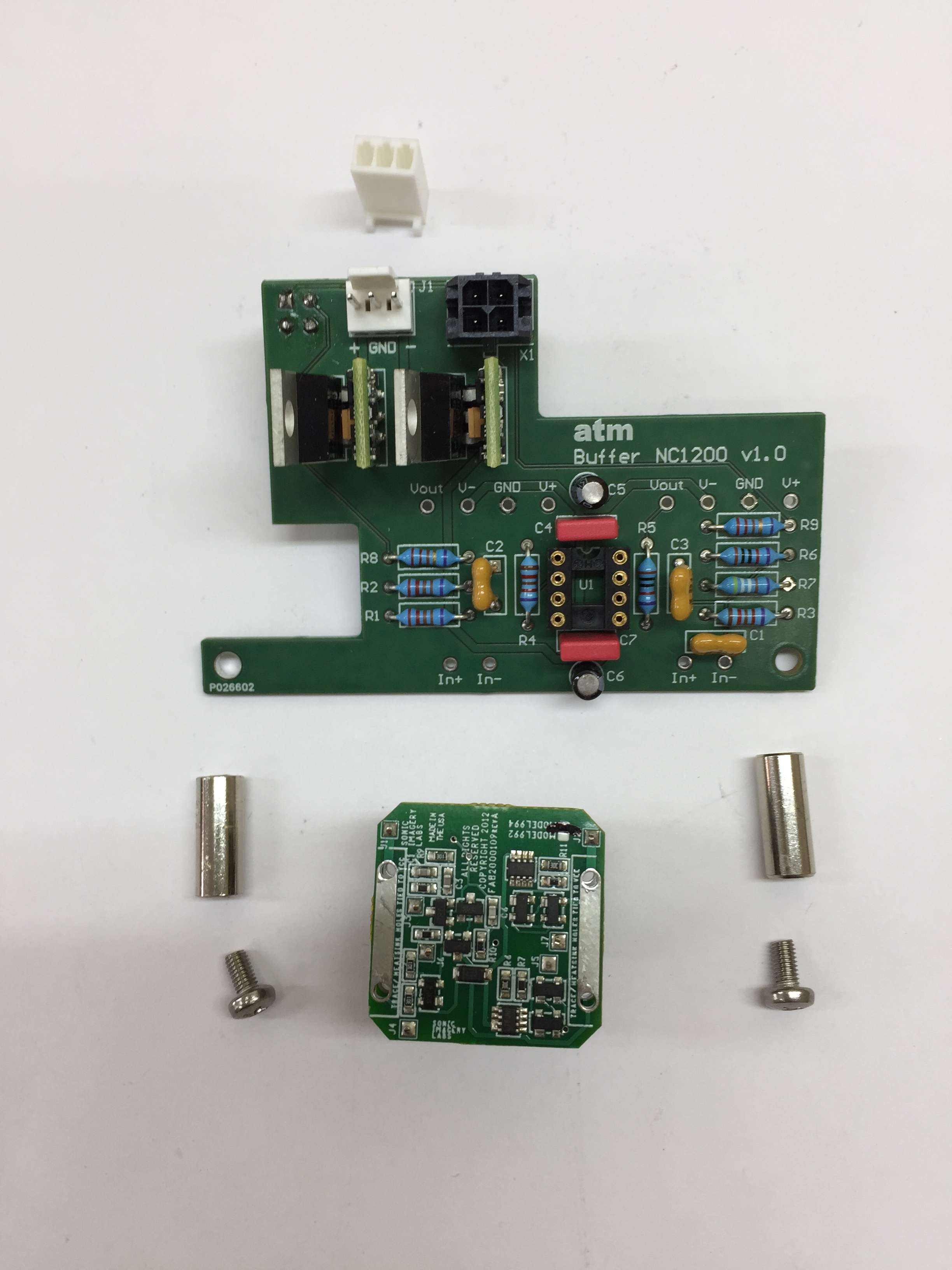
Figure 2. Components for a channel. The kit includes for two channels.
Unit Positioning
- Place the Buffer on a firm surface and check the condition of the kit.
- Screw the two spacers included in the kit into the screws protruding from the Hypex NC1200 power module, as shown in Figure 3 (A).
- Disconnect the audio input cable from the NC1200 module connector Figure 3 (B). This cable will be reused later.
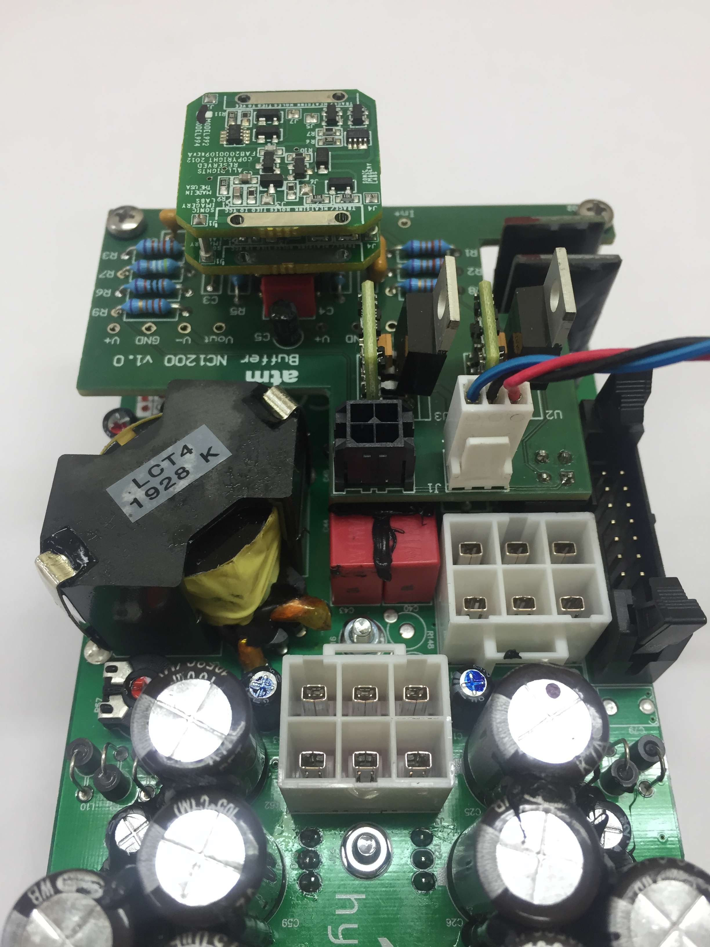
- Place the NC1200 Buffer PCB carefully and insert the black Molex connector from the bottom of the Buffer, matching it with the NC1200 module connector (Figure 3B). In turn, match the holes at the ends of the Buffer with the spacers indicated in point 2. Figure 4.
- Attach the M3 screws included in the kit to the spacers. Figure 5
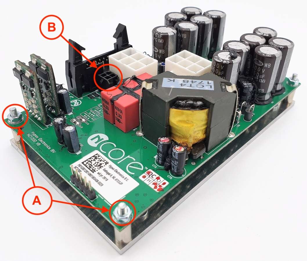
Figure 3.
Figure 3A. Placement of the separators.
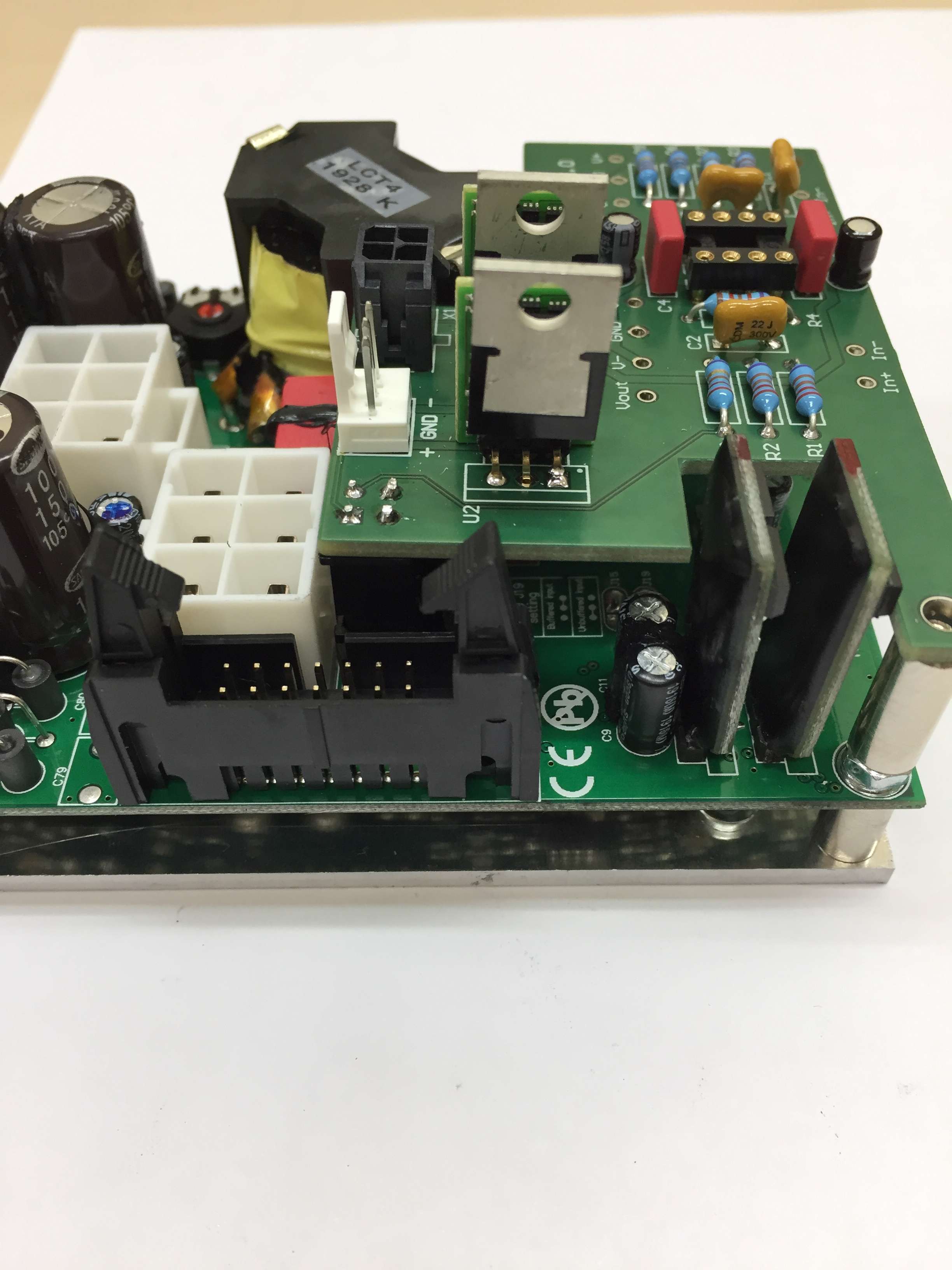
Figure 4. Placing the NC1200 Buffer board in the Hypex module.
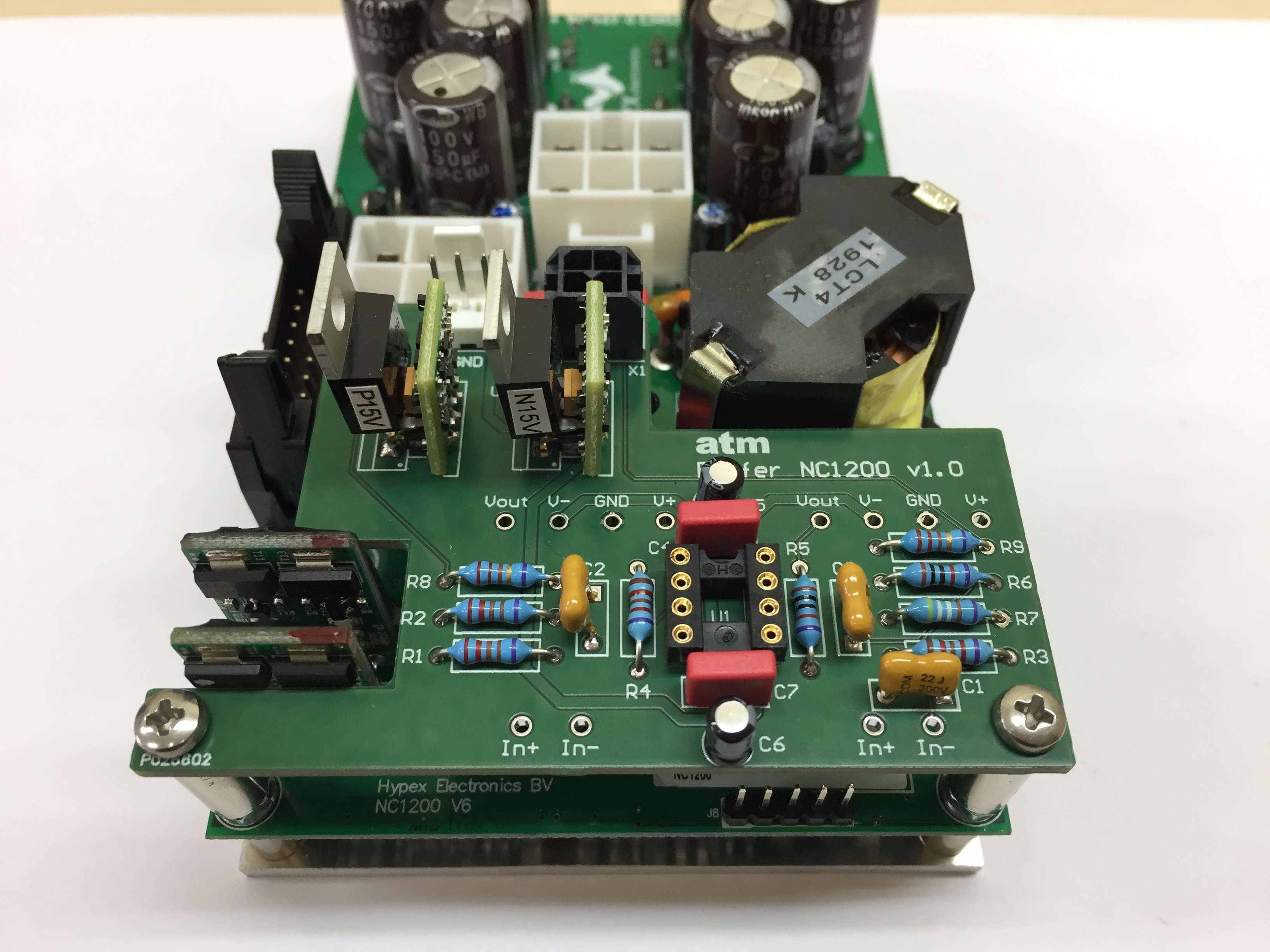
Figure 5. Fixing the M3 screws.
Unit wiring
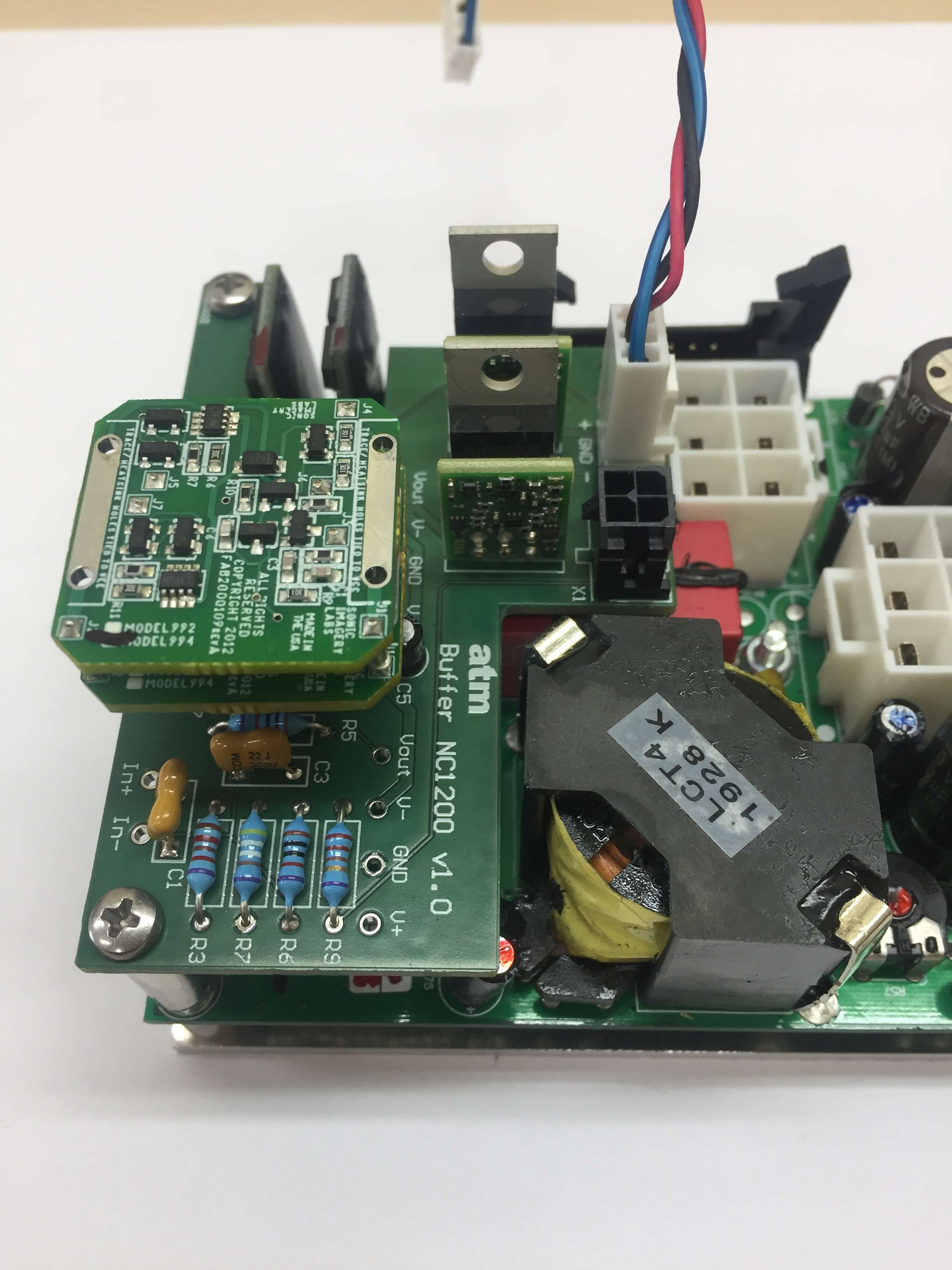
- Connect the cable removed at point 3, to connector X1 of the Buffer (figure 6)
- Connect the supplied power cable to connector J1 of the Buffer. (figure 7). This cable provides +/- 15V power to the Buffer and can be connected to the Hypex SMPS1200 source that provides power to the NC1200 module. (Connector J5, positions 3 (+), 5 (GND) and 7 (-) Refer to the SMPS1200 source service manual page 10. Observe the polarity of the connector. A wrong connection can cause an irreversible fault NOT covered by the warranty.
- Insert the operational amplifier (if not inserted) into the socket marked U1 (figures 8 and 9). Note the polarity notch. Incorrect insertion of the operational amplifier may cause an irreversible fault NOT covered by the warranty.
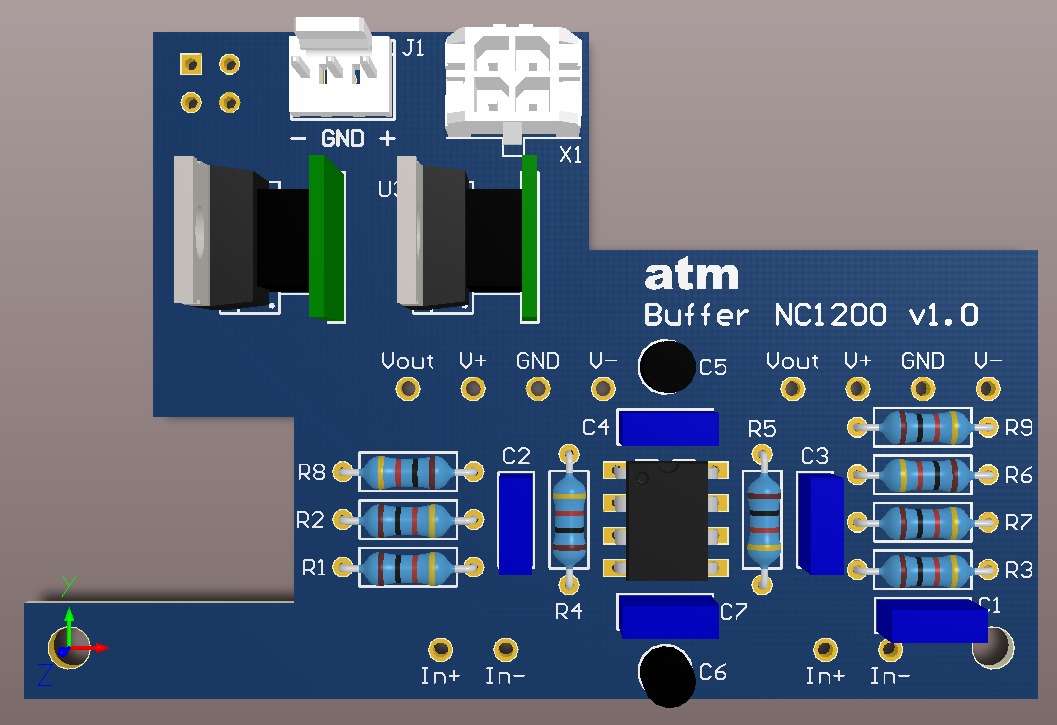
Figure 6.
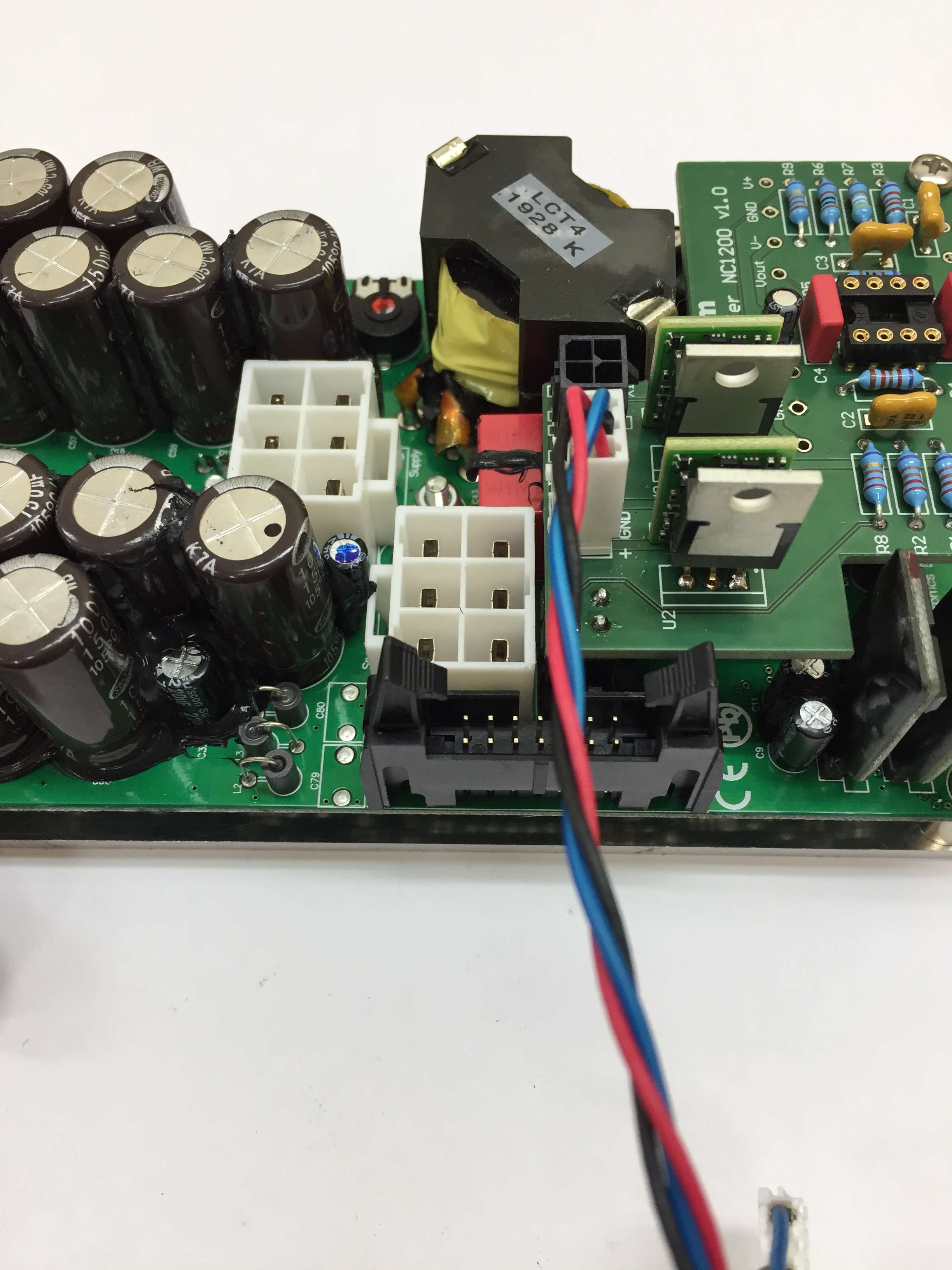
Figure 7. Positioning the power connector.
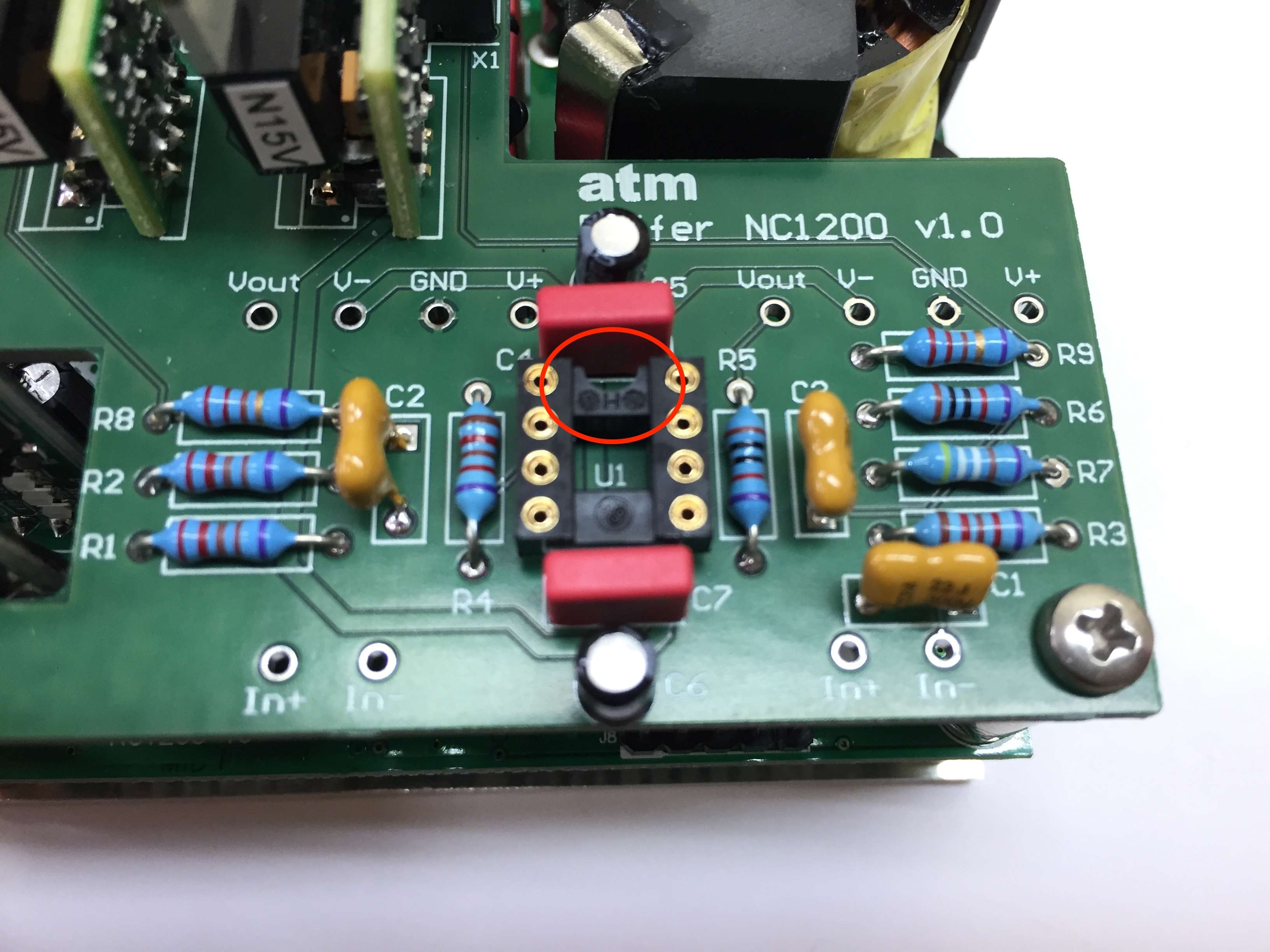
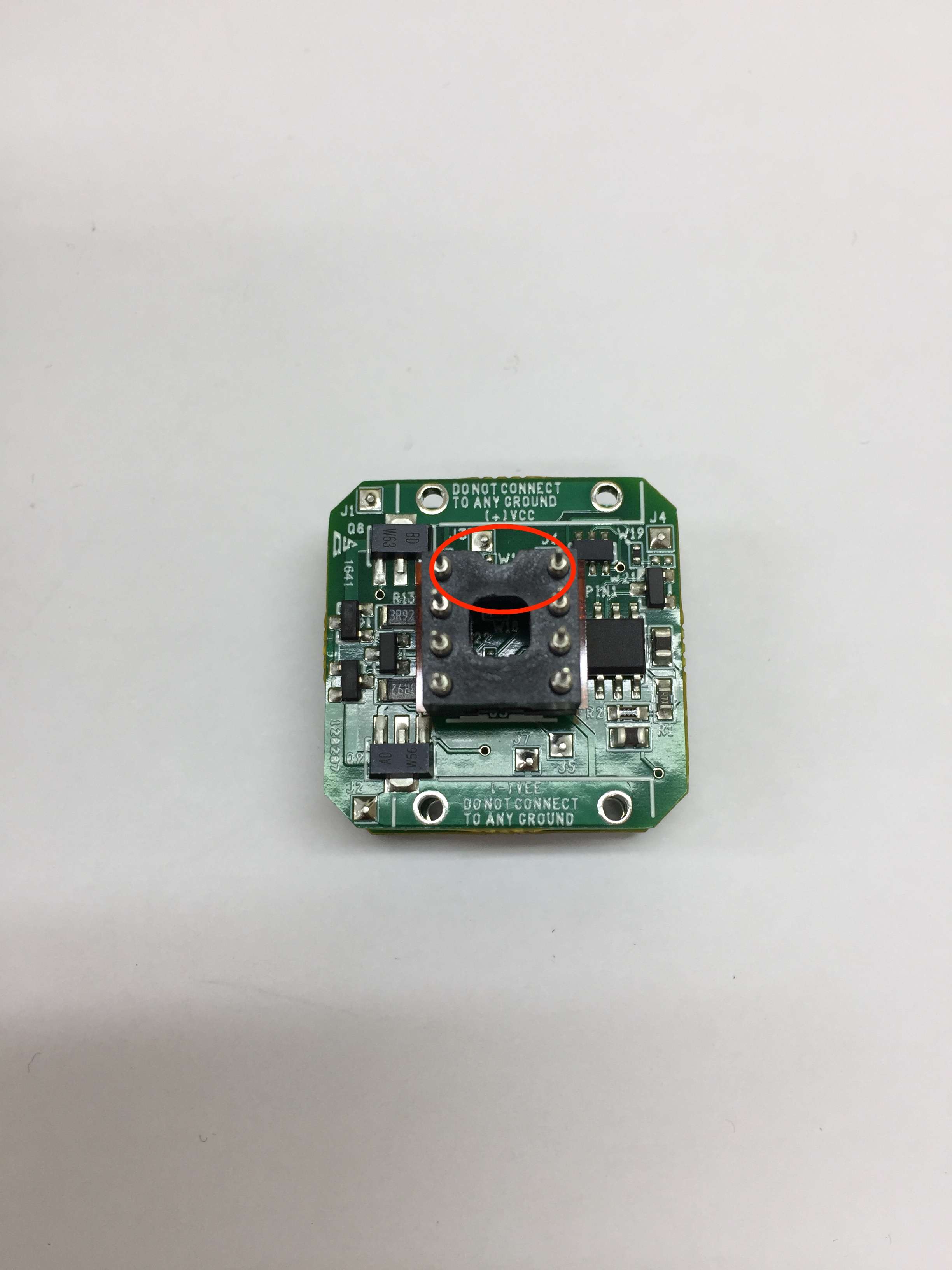
Figure 8. Insertion of the operational amplifier into socket U1.
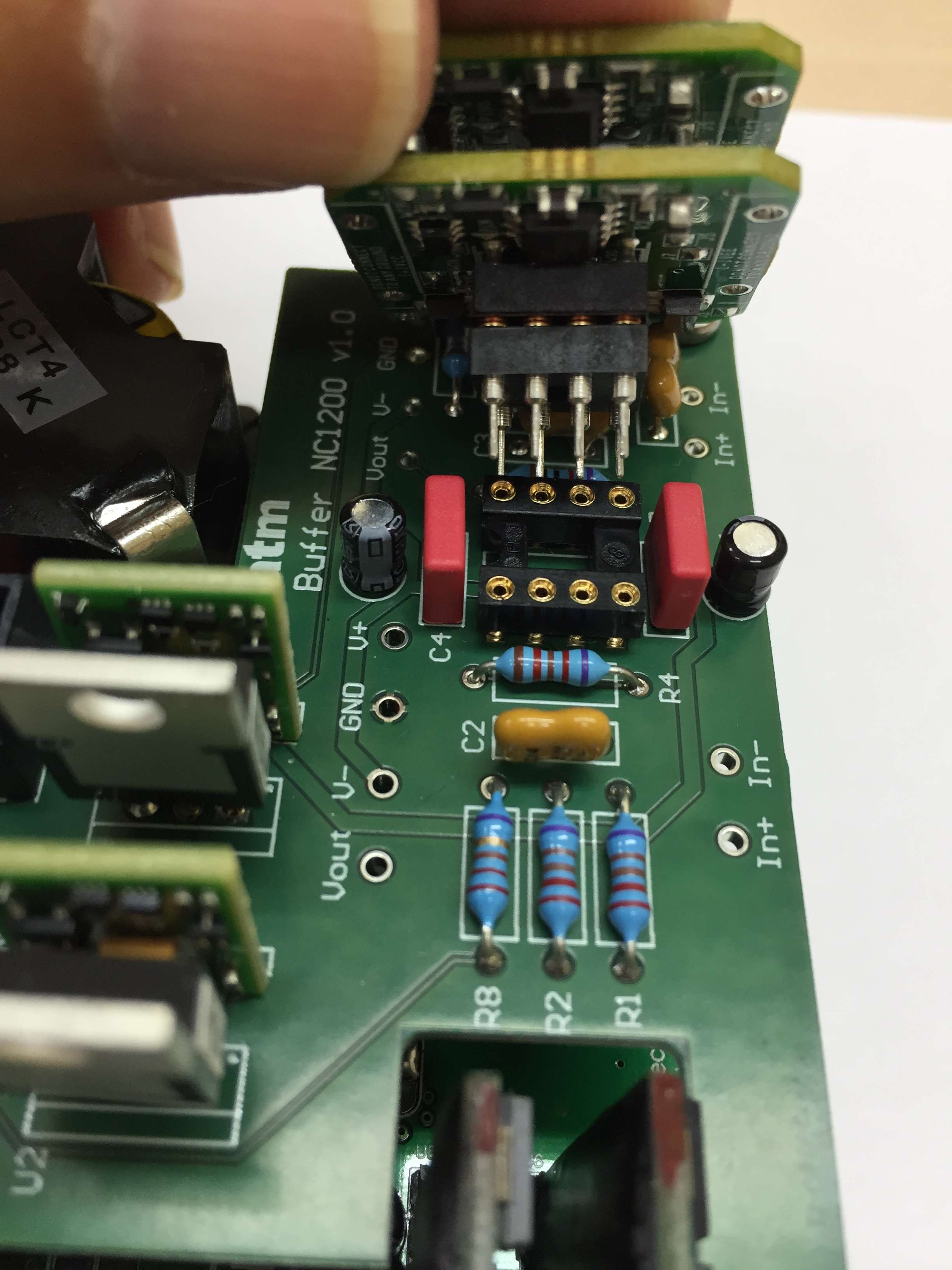
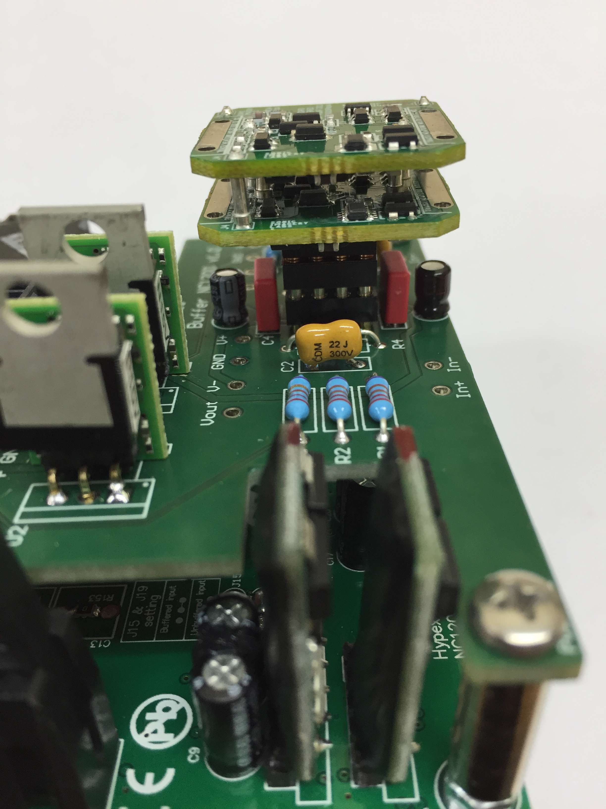
Figure 9. Insertion of the operational amplifier into socket U1.
The Buffer should be installed as indicated in the following figures.
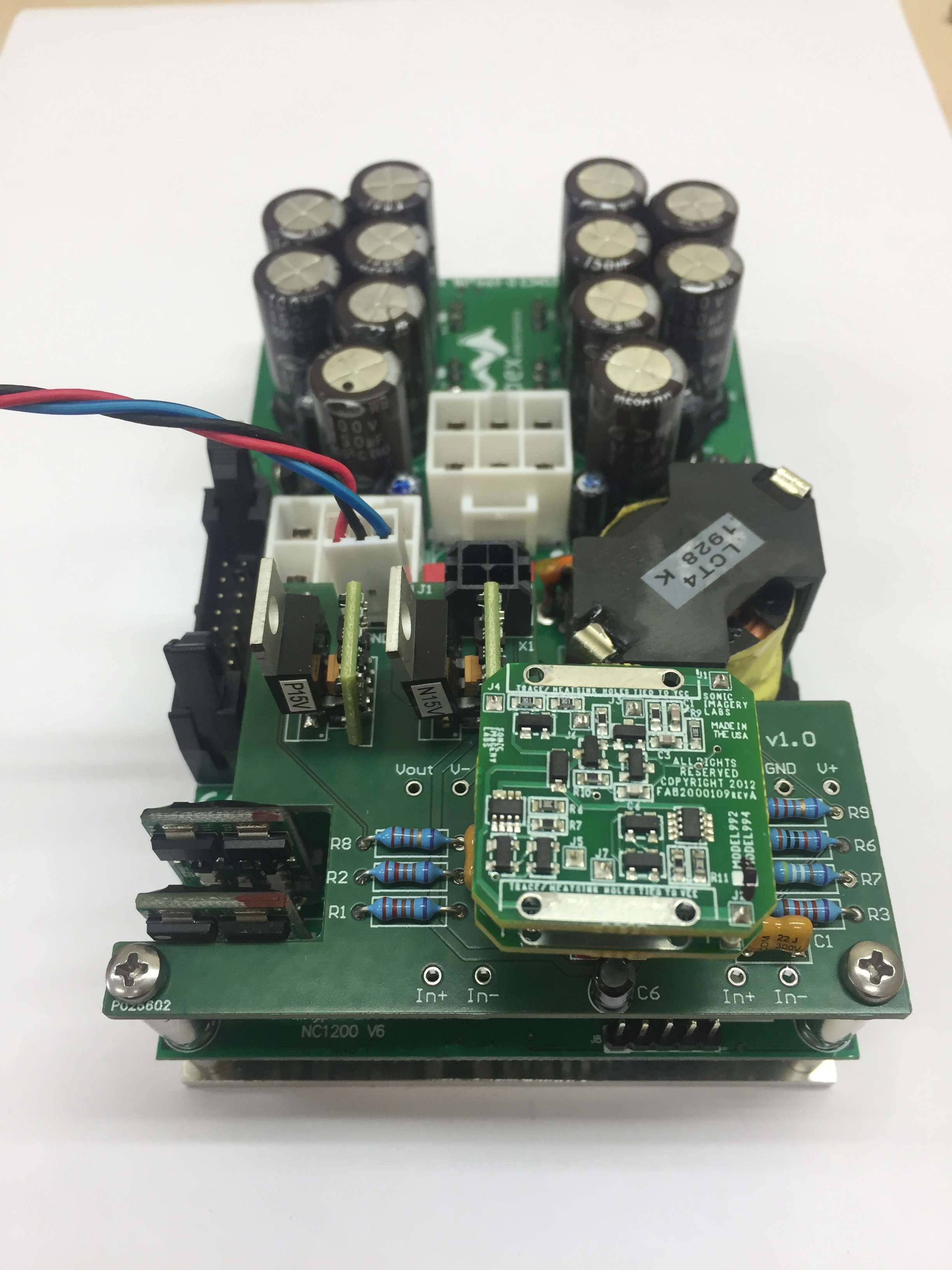
Once the board is installed in the power module, check that everything is connected correctly and reassemble the amplifier. The Buffer should run smoothly after applying the supply voltage.
No Comments