23 Sep Class A Power Amplifier model EPM-50 mono
EPM-50 mono, power amplifier development.
We started with the development of a new power stage in Class A.
Based on our EPM1 model (of which there will be a new update shortly) we have developed a new model that will have more power output, about 50W (just double that of the previous model).For this we will use 50% more output transistors that will supply more current, thus increasing the power.
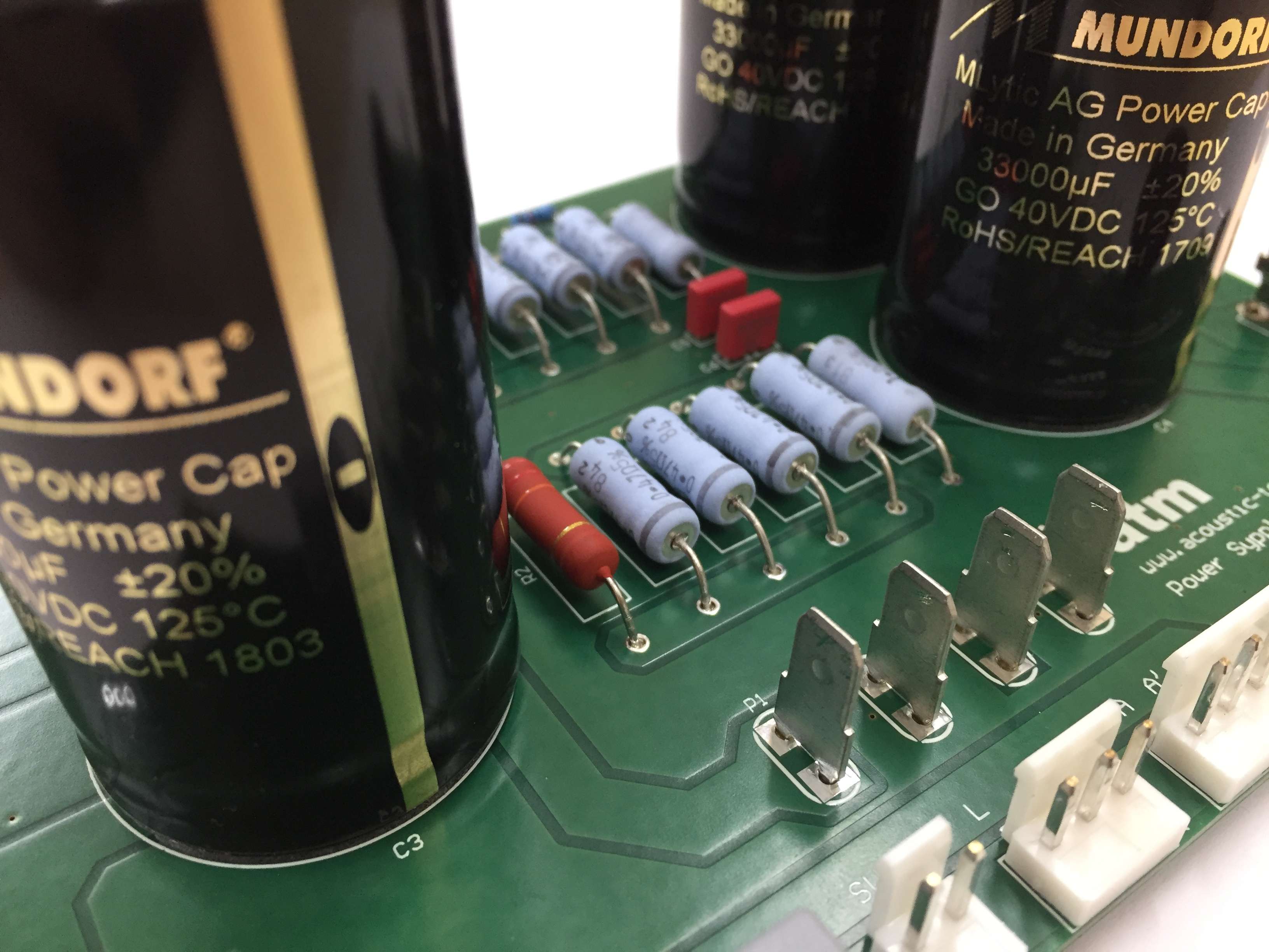
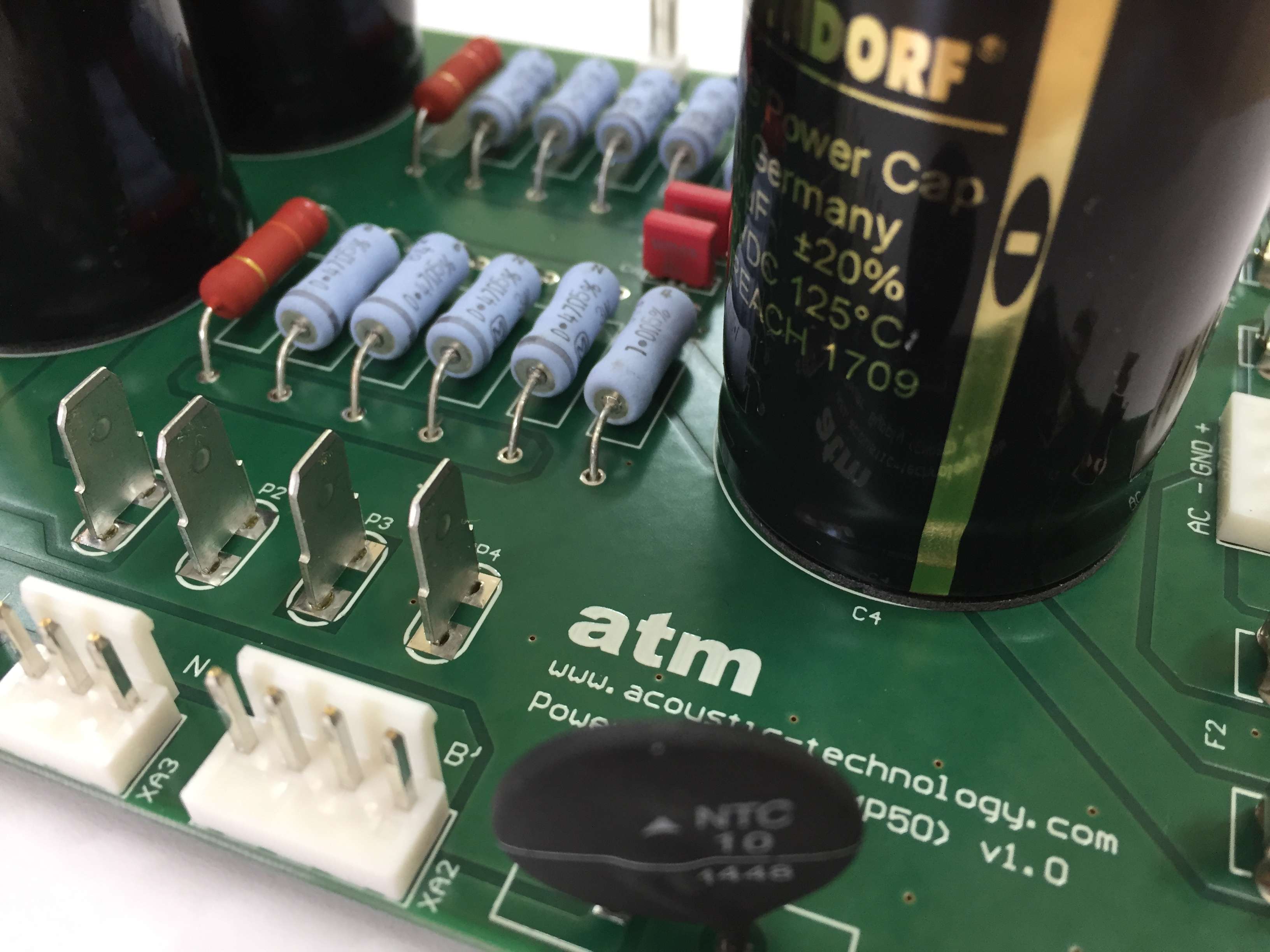
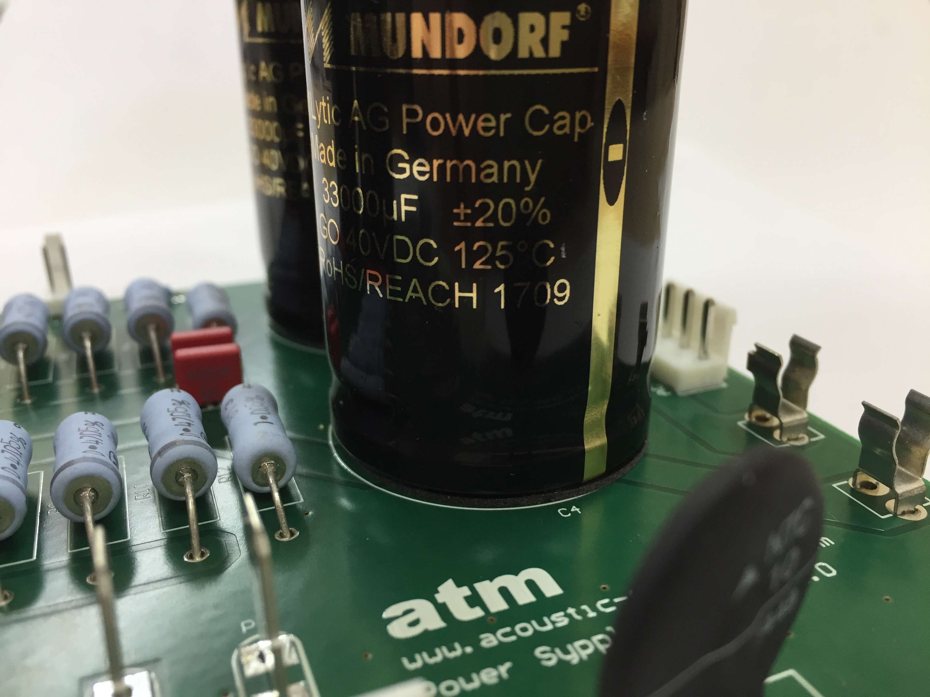
We start with the power supply which is based on a very low noise and low dispersion 400W toroidal transformer, high speed rectifier diodes and a CRC filter with Panasonic metal oxide resistance, Wima polyester capacitors for RFI / EMI removaland very low resistance Mundorf MLytic series electrolytic capacitors with a total capacity of 132,000uF
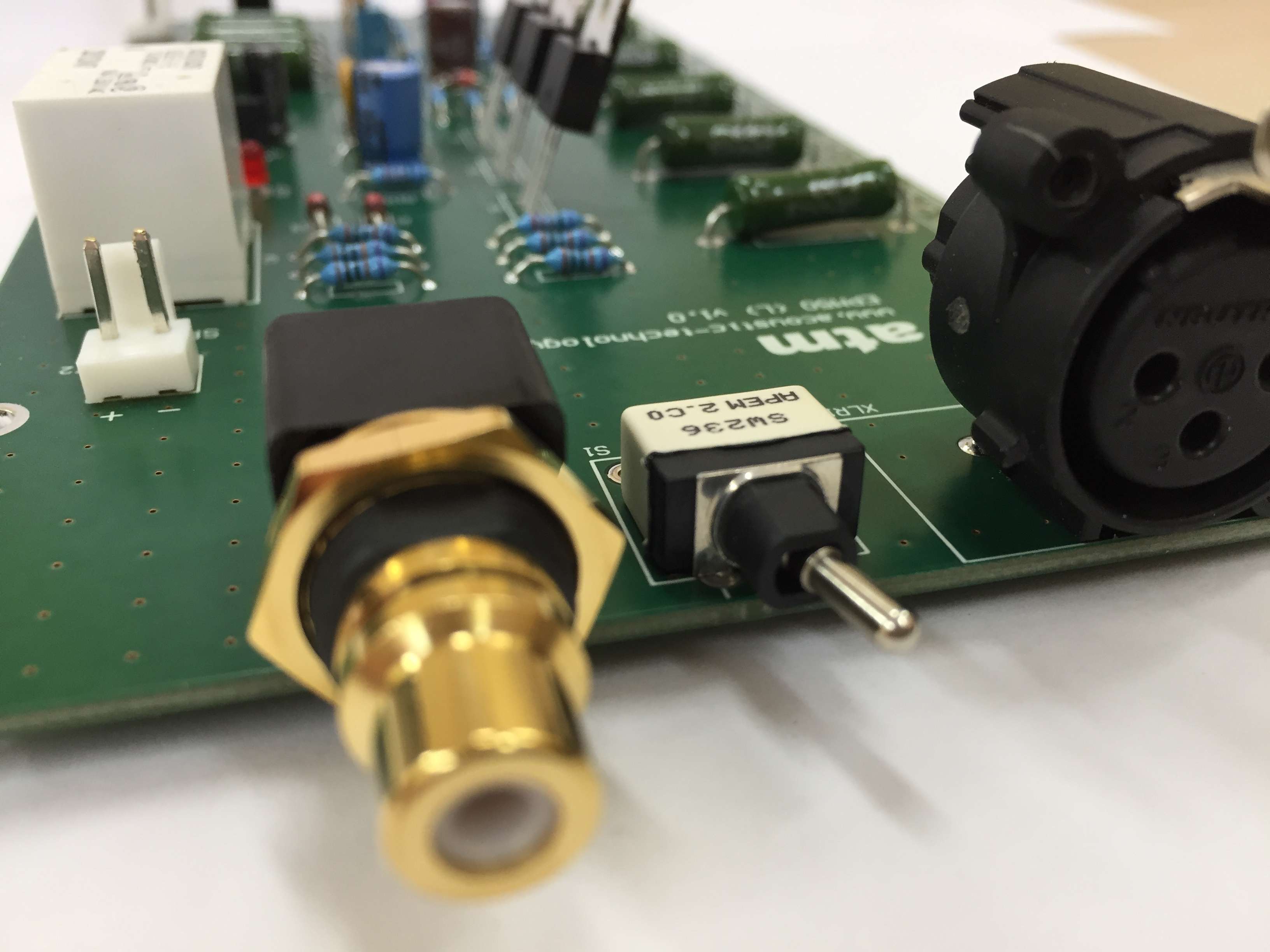
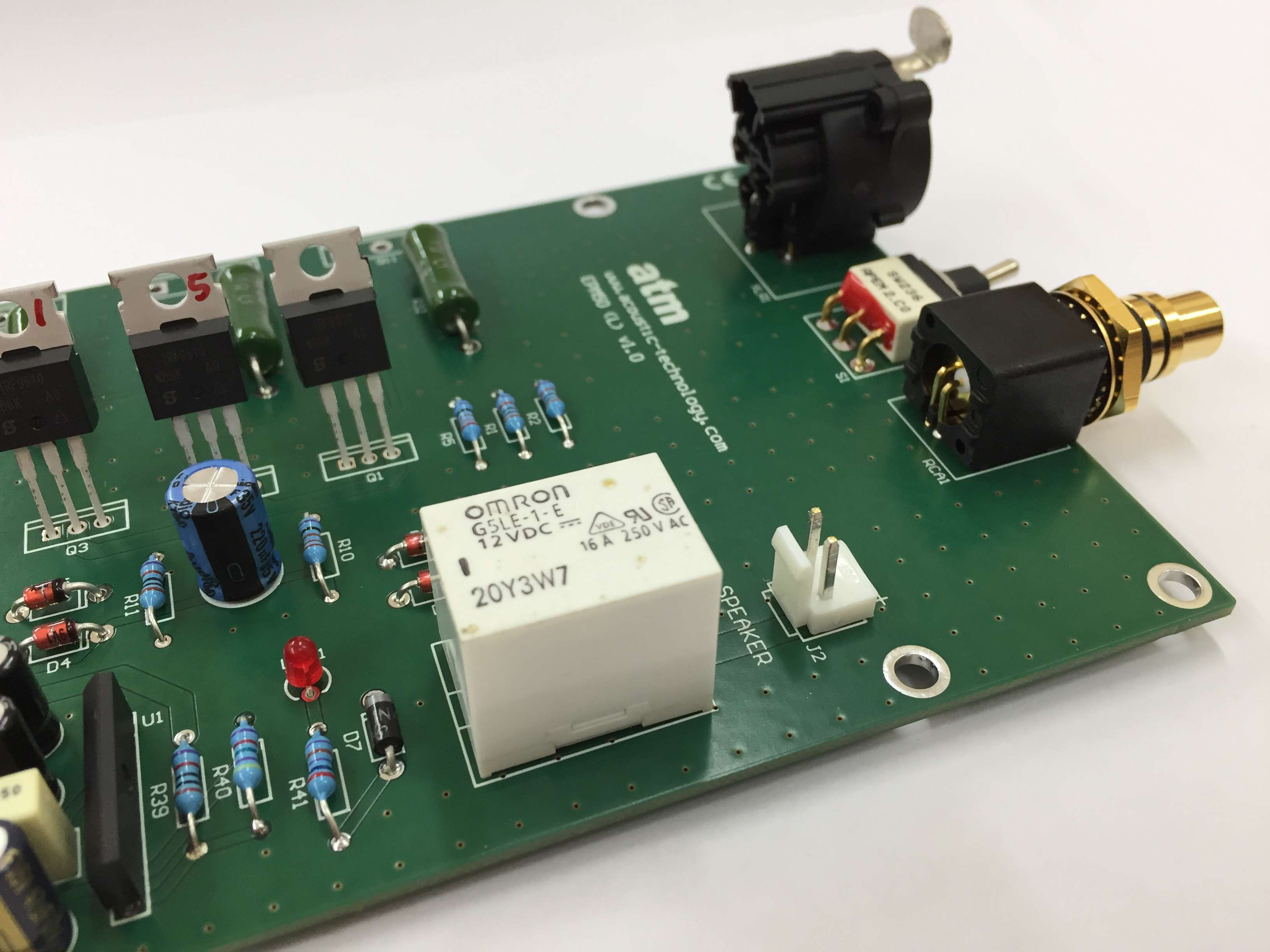
We continue with the main board, which has an RCA input and a balanced XLR with a selector switch.
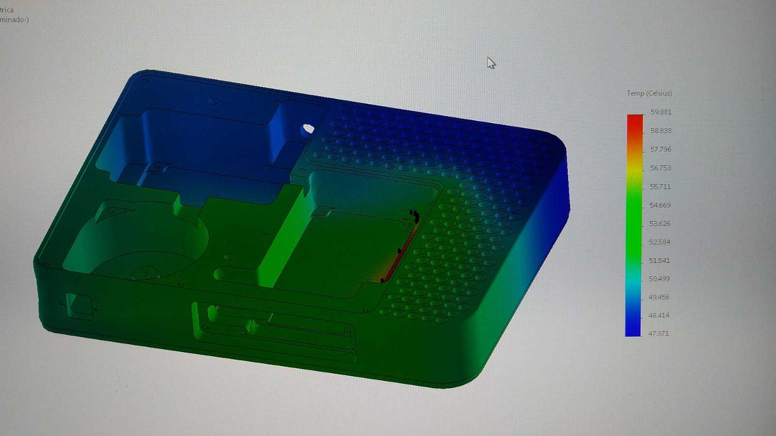
Once the printed circuit boards were assembled, both from the power supply and from the power section, we proceeded to design a new chassis and make a thermal study of it. Initially, it was thought to make the same monoblock structure as the EPM1 model and adapt the electronic ones, but the thermal dissipation was very high and compliance problems could arise.
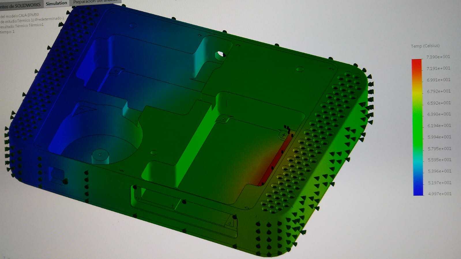
In the end, given the excess consumption and the great thermal dissipation it had, an aluminum chassis was used for each channel, that is, an independent monophonic unit, so we managed to lower the thermal dissipation to more reasonable levels.
For aesthetic reasons, we have designed them mirrored.
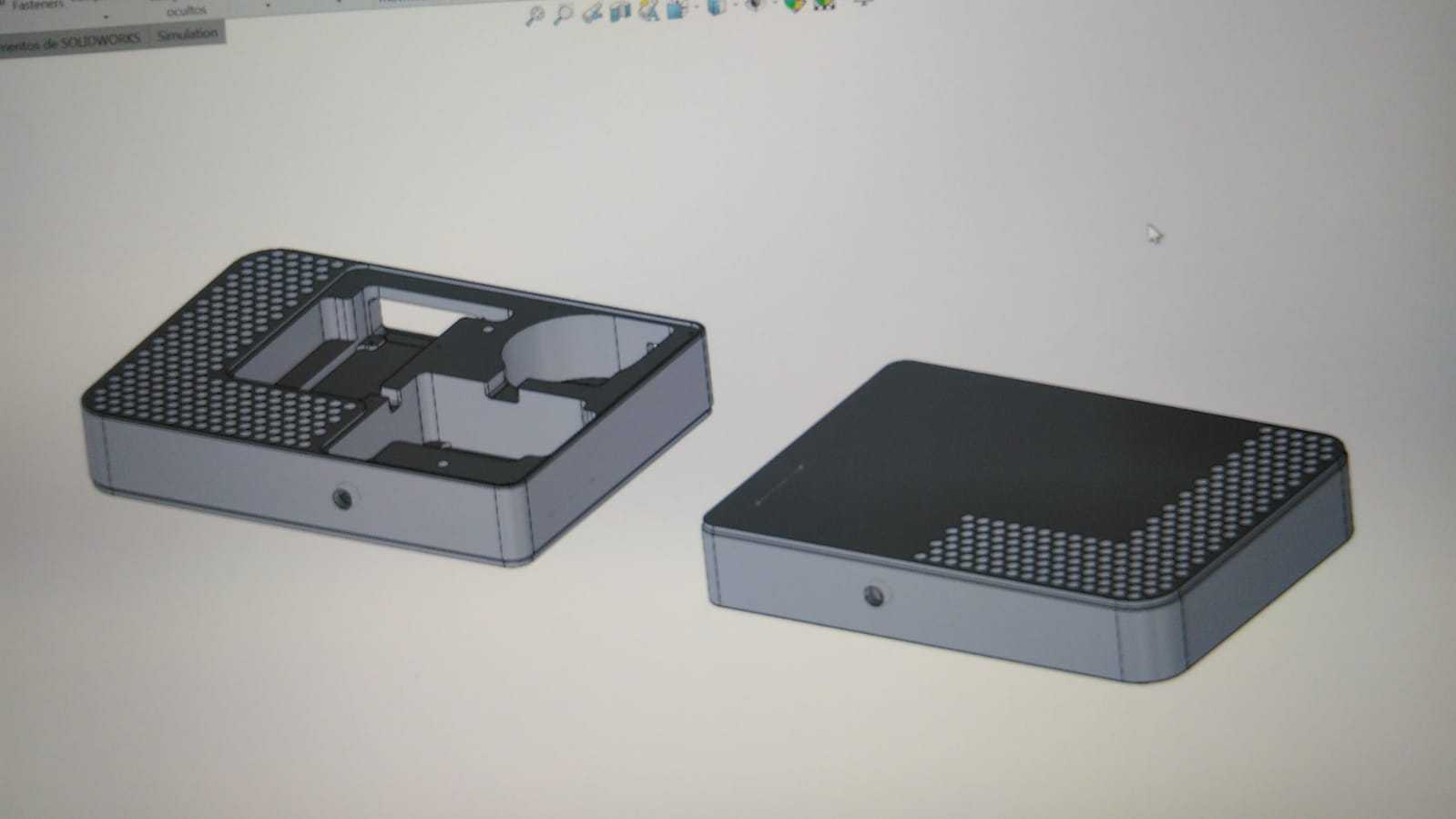
Once the thermal calculations have been carried out and verifying that they are within the regulations, we proceed to mechanize the boxes.


When the boxes are finished, the printed circuit boards of the power module and the power supply are mounted. The toroidal transformer is installed and everything is wired provisionally. The bias is adjusted at time intervals until the maximum working temperature is reached after two hours of uninterrupted operation.


Once verified that it does not exceed the temperature limits set by the regulations, we proceed to disassemble everything to take it to anodize. In this case, as it was a team that was destined for an exhibition, the base was painted in a striking way in red and the cover in silver, to contrast.


Once painted, all the components were reassembled inside the box, it was verified that it worked correctly, the cover was put on and the equipment was left running during the whole day (about eight hours). Thermal camera photos were taken to verify that the temperature was within the established limits.


The equipment is thus ready for use.


You can see the video of the assembly process on our YouTube channel.
No Comments